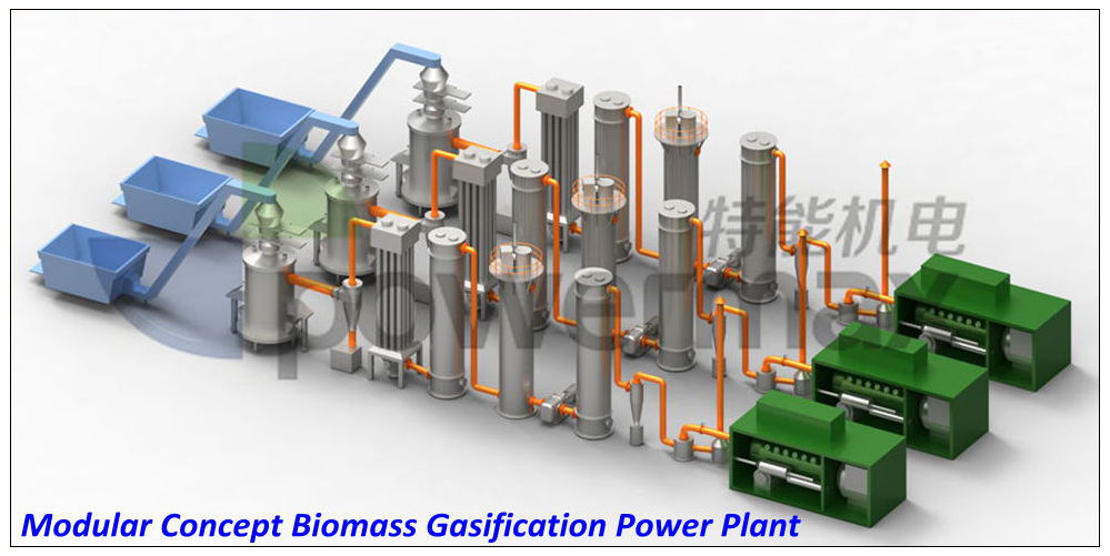
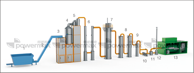
- 1. Biomass Storage
- 2. Biomass Conveyor
- 3. Biomass Buffer Bin
- 4. Biomass Gasifier
- 5. Cyclone Dust Collector
- 6. Gas Filter
- 7. ESP
- 8. Gas Scrubber
- 9. Gas Dryer
- 10. Blower
- 11. Buffer Tank
- 12. Gas Flare
- 13 Gas Generator Sets

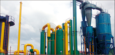
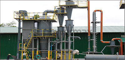
Rice Husk Gasification Power Plant

Rice Husk Gasification Power Plant
| System Series | CFBG Series | DFBG Series |
| Power Range | 200 – 2000 kW | 50 – 1000 kW |
| Gasifier Type | Circulating Fluidized Bed | Downdraft Fixed Bed |
| Moisture Requirement | ≤20% | ≤16% |
| Gas Calorific Value | 1200–1300 kcal/Nm³ | ≥1100 kcal/Nm³ |
| Purification System | Semi‑Dry Type | Dry Type |

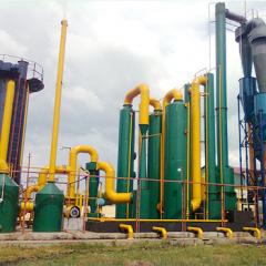
POWERMAX Rice Husk Gasification Power Plant
The POWERMAX rice husk biomass gasification power generation system (BGPS) converts rice husk (also called rice hull) into combustible gas, which is then used as fuel in a gas engine to generate electricity. Biomass gasification overcomes key disadvantages of rice husk, such as low flammability and inconsistent quality. With a small footprint and environmentally friendly operation, it is one of the most efficient ways to utilize biomass for power generation.
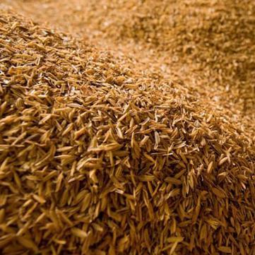
Key Requirement for Rice Husk Fuel
To ensure optimal performance in the rice husk gasification power plant, the moisture content of the rice husk must be less than 20%.
How the Rice Husk Gasification Power Plant Works
The process consists of three main steps:
- Biomass gasification – Rice husk is converted into syngas in the gasifier.
- Syngas purification – The raw gas passes through a purification system that removes dust, tar, and other contaminants to protect the gas engine.
- Power generation – The clean gas fuels a gas engine to produce electricity. Waste heat from the engine can be recovered for steam or hot water, and a combined cycle with a steam turbine can further increase overall efficiency.
Technology & System Models
POWERMAX offers modular rice husk gasification power generation systems covering capacities from 50 kW to 20 MW, with two main series designed specifically for rice husk:
- CFBG Series (Circulating Fluidized Bed Gasifier) – Suitable for 200 kW to 2000 kW applications. It accepts rice husk with moisture ≤20% and particle size ≤8–15 mm, delivering a gas calorific value of 1200–1300 kcal/Nm³.
- DFBG Series (Downdraft Fixed Bed Gasifier) – Ranges from 50 kW to 1000 kW. Requires rice husk moisture ≤16% and particle size less than 1 cm, producing syngas with a calorific value ≥1100 kcal/Nm³.
Both series integrate high‑efficiency generator sets (500–1000 rpm or 1500 rpm) equipped with Siemens alternators and advanced European engine control systems. Compared to conventional boiler‑fired systems, POWERMAX biomass gasification plants deliver a highly competitive solution for reliable rice husk electricity generation.
POWERMAX CFBG Power Plant
Our CFBG system can directly use rice husk!
Technical Specification of CFBG series Biomass Gasification Power Generation System
CFBG Series Technical Specifications
| Model | 200CFBG | 400CFBG | 500CFBG | 600CFBG | 800CFBG | 1000CFBG | 1200CFBG | 1500CFBG | 2000CFBG |
| Rated Power(kw) | 200 | 400 | 500 | 600 | 800 | 1000 | 1200 | 1500 | 2000 |
| Rated Frequency | 50 /60 HZ | ||||||||
| Rated Voltage(V) | 220 / 400 / 440 / 6300 / 6600 / 11000 /13800 | ||||||||
| Model of Gasifier | CFBG200 | CFBG400 | CFBG500 | CFBG600 | CFBG800 | CFBG1000 | CFBG1200 | CFBG1500 | CFBG2000 |
| Gasifier Type | Circulating Fluidized Bed Gasifier(CFBG) | ||||||||
| Biomass Moisture Requirement | ≤20%(wet basis) | ||||||||
| Biomass Size Requirement | ≤8-15mm | ||||||||
| Biomass Consumption(Kg/hr) | 200-360 | 400-720 | 500-900 | 600-1080 | 800-1440 | 1000-1800 | 1200-2160 | 1500-2700 | 2000-3600 |
| Gas Production(Nm3/h) | 500-600 | 1000-1200 | 1250-1500 | 1500-1800 | 2000-2400 | 2500-3000 | 3000-3600 | 3750-4500 | 5000-6000 |
| Ash Discharge Type | Dry Ash Type | ||||||||
| Type of Gas Purification | POWERMAX Semi Dry Type Gas Purification System | ||||||||
| Heat Value of Gas | 1200-1300Kcal/Nm3 | ||||||||
| Gas Composition | CO-12~18%, CO2-10~16%, CH4-4~8% H2-3~7% CnHm-1~1.4% O2-0.5~1.2% N2-54~60% | ||||||||
| Model of Gensent | 100GFLS | 400GFLS | 500GFLS | 300GFLS | 400GFLS | 1000GFLS | 400GFLS | 500GFLS | 1000GFLS |
| Qty of Genset | 2 | 1 | 1 | 2 | 2 | 1 | 3 | 3 | 2 |
-
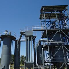
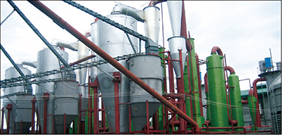
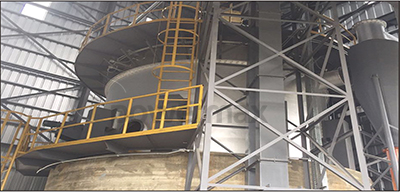
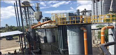
2MW CFBG POWER PLANT
-
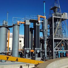
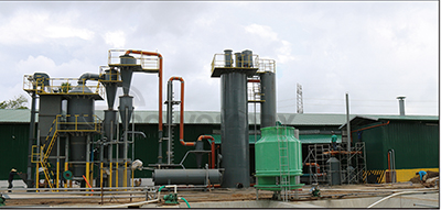
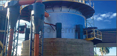
0.5MW CFBG POWER PLANT-2
-
3MW CFBG POWER PLANT
-
0.5MW CFBG POWER PLANT


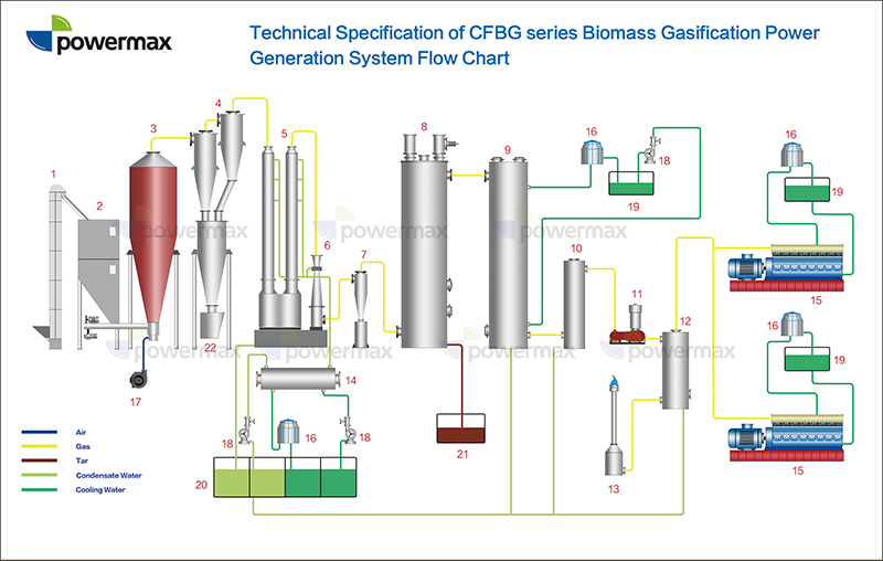
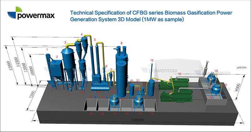
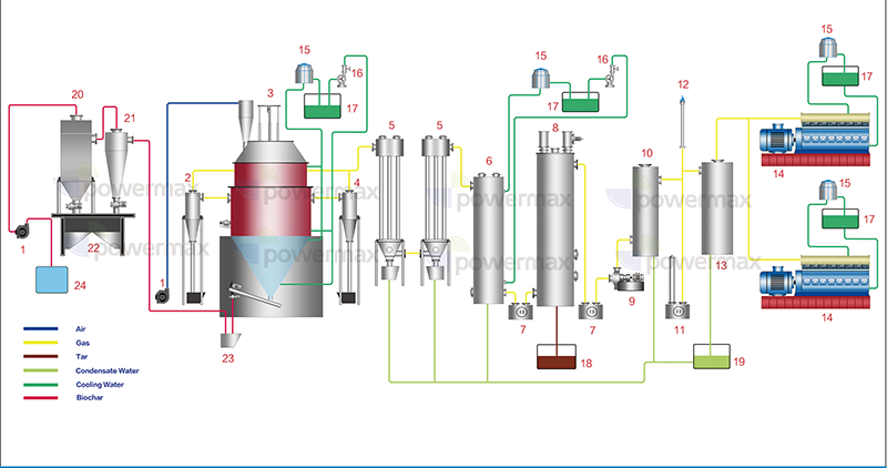
- 1.Elevator
- 2.Feed Bin
- 3.Gasifier
- 4.Cyclone
- 5.Tube Type Dust Remover
- 6.Venturi
- 7.Cyclone Hydraulic Separators
- 8.ESP
- 9.Indirect Cooler
- 10.Water Drop Catcher
- 11.Roots Blower
- 12.Buffer Tank
- 13.Vent Cans&Gas Flare
- 14.Tubular Heat Exchanger
- 15.Gas Generator Set
- 16.Cooling Tower
- 17.Air Blower
- 18.Water Pump
- 19.Cooling Water Pool
- 20.Condensate Water Pool
- 21.Tar Tank
- 22.Biochar Outlet
POWERMAX DFBG Power Plant
Our DFBG system can directly use rice husk!

- 1. Biomass Storage
- 2. Biomass Conveyor
- 3. Biomass Gasifier
- 4. Cyclone Dust Collector
- 5. Air Cooler
- 6. Gas Cooler
- 7. ESP
- 8. Gas Cooler
- 9. Gas Dryer
- 10. Buffer Tank
- 11. Gas Flare
- 12. Gas Generator Sets
- 13. Blower
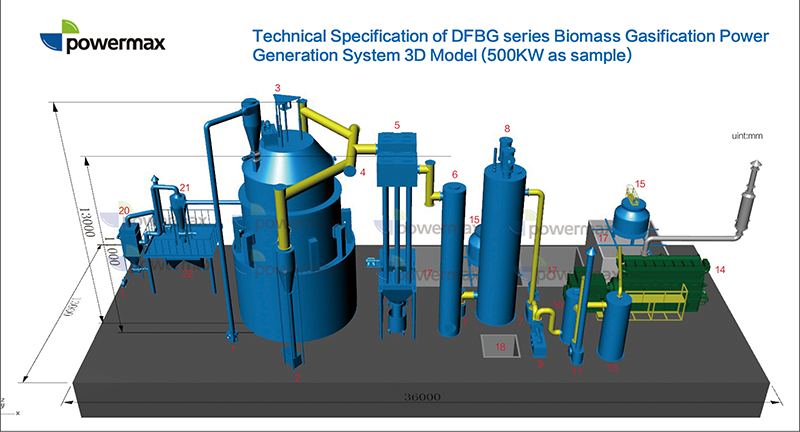
Technical Specification of DFBG series Biomass Gasification Power Generation System
DFBG Series Technical Specifications
| Model | 50DFBG | 100DFBG | 200DFBG | 300DFBG | 400DFBG | 500DFBG | 600DFBG | 800DFBG | 1000DFBG |
| Rated Power(kw) | 50 | 100 | 200 | 300 | 400 | 500 | 600 | 800 | 1000 |
| Rated Frequency | 50 /60 HZ | ||||||||
| Rated Voltage(V) | 220 / 400 / 440 / 6300 / 6600 / 11000 /13800 | ||||||||
| Model of Gasifier | DFBG50 | DFBG100 | DFBG200 | DFBG300 | DFBG400 | DFBG500 | DFBG600 | DFBG800 | DFBG1000 |
| Gasifier Type | Downdraft Fixed Bed Gasifier | ||||||||
| Biomass Moisture Requirement | ≤16%(wet basis) | ||||||||
| Biomass Size Requirement | Less than 1cm | ||||||||
| Biomass Consumption(Kg/hr) | 50-100 | 100-200 | 200-400 | 300-600 | 400-800 | 500-1000 | 600-1200 | 800-1600 | 1000-2000 |
| Gas Production(Nm3/h) | 125-150 | 250-300 | 500-600 | 750-900 | 1000-1200 | 1250-1500 | 1500-1800 | 2000-2400 | 2500-3000 |
| Ash Discharge Type | Dry Ash Type | ||||||||
| Type of Gas Purification | Dry Type Gas Purification System | ||||||||
| Heat Value of Gas | ≥1100Kcal/Nm3 | ||||||||
| Gas Composition | CO-15~20%, CO2-8~12%, CH4-upto 4% H2-10~15% N2-45~55% | ||||||||
| Model of Gensent | 50GFLS | 100GFLS | 100GFLS | 300GFLS | 400GFLS | 500GFLS | 300GFLS | 400GFLS | 1000GFLS |
| Qty of Genset | 1 | 1 | 2 | 1 | 1 | 1 | 2 | 2 | 1 |
-
1MW DFBG POWER PLANT

-
1MW DFBG POWER PLANT-2
-
1MW DFBG POWER PLANT
-
0.8MW DFBG POWER PLANT


- 1.Biomass Fuel Blower
- 2.Cyclone
- 3.Gasifier
- 4.Cyclone
- 5.Air Cooler
- 6.Indirect Cooler
- 7.Isolation Seal
- 8.ESP
- 9.Booster Fan
- 10.Water Drop Catcher
- 11.Water Bleeding
- 12.Gas Flare
- 13.Buffer Tank
- 14.Gas Generator Set
- 15.Cooling Tower
- 16.Water Pump
- 17.Cooling Water Pool
- 18. Tar Tank
- 19.Condensate Water Pool
- 20.Pulse Dust Collector
- 21.Cyclone Dust Collector
- 22.Ash Tank
- 23.Ash Discharge Transition Hopper
- 24.Water Tank
Feedback form contact with us